
P-Net_Getting_Started_Guide.md 14 KB
P-NET-RTT
This repository is a port of the open-source P-Net evaluation version to RT-Thread, used for implementing the P-Net protocol stack for Profinet devices.
1. Preliminary Setup
Software Environment
- CODESYS (Profinet master simulation)
- CODESYS
- CODESYS Gateway (Gateway device)
- CODESYS Control Win SysTray (SoftPLC device)
- Npcap (This software is required for running CODESYS and must be installed in advance!)
- PRONETA
Hardware Environment
- Microcontroller with ETH (Ethernet driver must support RT-Thread Ethernet driver framework)
2. Software Package Configuration
Open the bsp's env interface, go to ->RT-Thread online packages->IoT, and find [*] P-Net stack for Profinet device implementation ---> to enable it. Also, leave configurations for the user:
-*- Default netif name for P-NET  --->
	-> (e00) default ethernet interface name for p-net app, default as 'e00
-*- Enable P-NET sample board config  --->
	-> (0x0209) p-ent user led pin
	-> (0x0005) p-net user key pin
-*- Default root filesystem path for P-NET  --->
    -> [*] p-net using ramfs filesystem by default, or you can turn this off and choose another way to enable the filesystem
    -> (8192)  default memory size for ramfs
-*- P-NET sample slave network ip config  --->
    -> (192.168.10.100) set static ip address for profinet slaver
    -> (192.168.10.1) set static gateway address for profinet slaver
    -> (255.255.255.0) set static mask address for profinet slaver
    version (latest)  --->
- Default netif name for p-net: P-net network interface device name, default as e00.
- Enable pnet sample board config: Configuration for P-net app user LED and button.
- Default root filesystem path for p-net: P-net filesystem configuration, default using ramfs with 8KB memory space.
- P-NET sample slave network ip config: Static IP configuration for Profinet slave device (Make sure to disable RT_LWIP_DHCP feature and use static IP).
Next, configure DHCP to be disabled and use a static IP. Go to → RT-Thread Components → Network → LwIP: lightweight TCP/stack, and disable DHCP:

After completing the configuration, compile and download the program to the development board.
3. Network Configuration
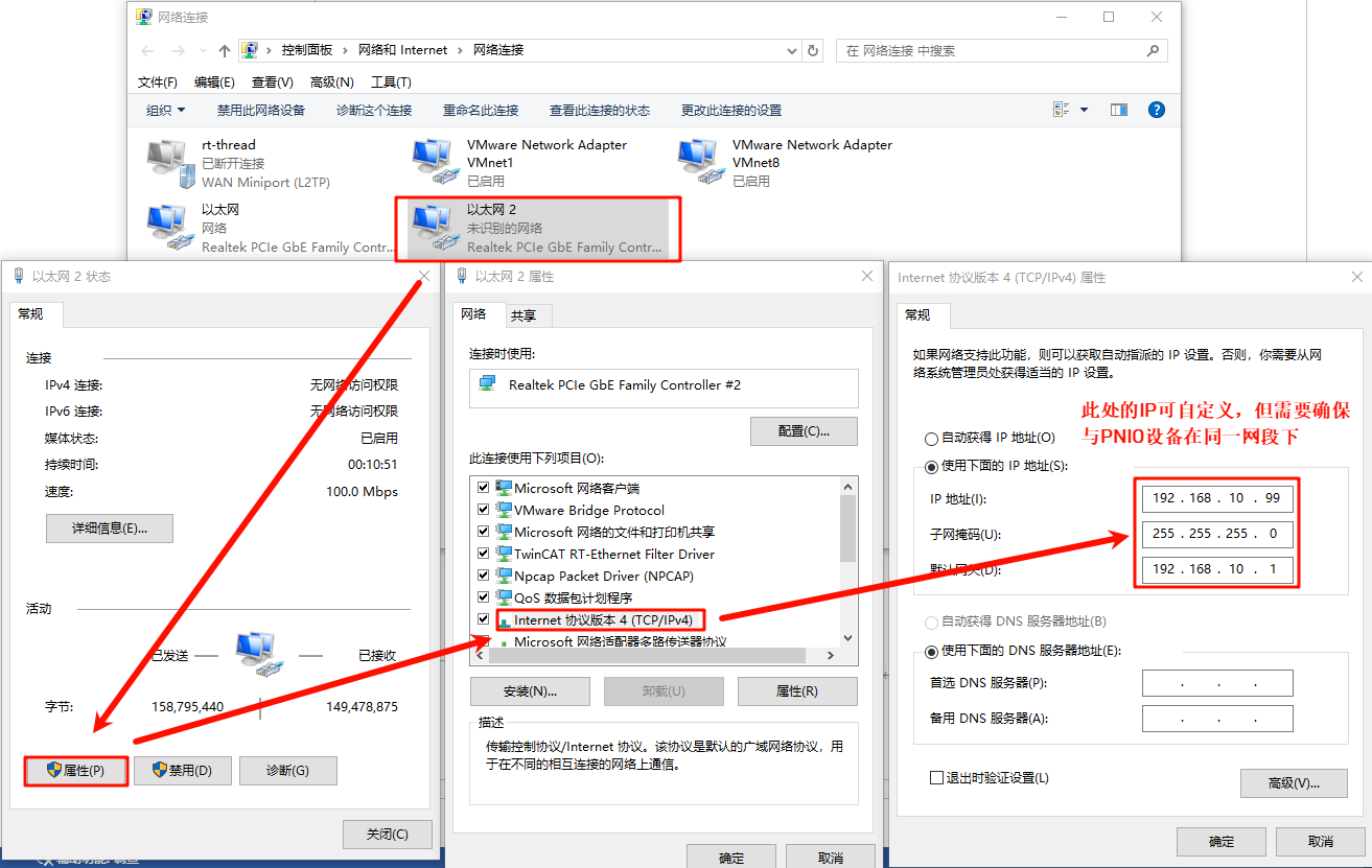
Connect the development board to the PC using an Ethernet cable, and configure a static IP on the PC side:
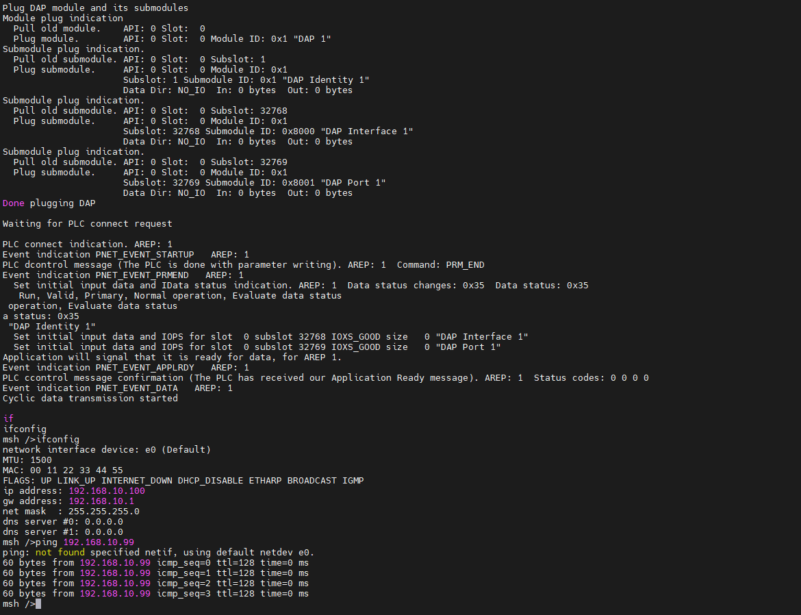
Check the IP information on the development board and test the connectivity:
4. SoftPLC Master Startup
CODESYS Overview: CODESYS is a PLC software developed by the German company 3S. It integrates functions like PLC logic, motion control, and configuration displays. CODESYS, short for "Controller Development System," is an industrial automation programming tool based on the IEC 61131-3 standard. It supports multiple programming languages (e.g., ladder diagram, structured text, function block diagram) and offers a wide range of libraries and functional modules, helping engineers quickly develop and debug PLCs and industrial control systems. Its flexibility and powerful features make it widely used in industrial automation.
4.1 Create a Standard CODESYS Project
Ensure that the CODESYS software is installed. After installation, the following three pieces of software will be used:

- CODESYS V3.5 SP20 Patch 3: Profinet master simulation
- CODESYS Gateway V3: Gateway device
- CODESYS Control Win V3 -x64 SysTray: SoftPLC device
First, open CODESYS V3.5 SP20 Patch 3, select -> New Project -> Projects -> Standard Project, configure the project name and location, then click OK:

After the following popup, keep the default Settings (CODESYS Control Win V3 (CODESYS)/x64 (CODESYS)) and click OK:

Note: If you purchased the CODESYS Control RTE SL, you can choose the device: CODESYS Control RTE V3 (CODESYS) / x64 (CODESYS). For normal evaluation purposes, you can skip installing this extension package and select CODESYS Control Win V3 (CODESYS) / x64 (CODESYS) device to create the project.
After the creation is successful, you will see the main interface:

4.2 Gateway and SoftPLC Startup
Open the following two software applications:
- CODESYS Gateway V3 (Right-click Start Gateway)
- CODESYS Control Win V3 -x64 SysTray (Right-click Start PLC)

Go back to the CODESYS master software, double-click Device (CODESYS Control Win V3 x64) -> Communication Settings -> Scan Network:

After the device user login window appears, configure the username and password (user-defined):

Check if the gateway device and softPLC device are online:

4.3 Add Profinet GSDML File
GSD (Generic Station Description) files: These are used in PROFIBUS DP (GSD files) and PROFINET IO (GSDML files) communication, acting as a bridge between the CPU module and IO modules in a PLC system. They typically include channel data, parameter data, diagnostic data, and user-defined data.
The GSDML file for this project is located at:
- ..\src\ports\rtthread\pn_dev
Install the GSDML file from the device repository by selecting GSDML-V2.4-RT-Labs-P-Net-Sample-App-20220324.xml under the above path:

After the installation is successful, you will see the P-net slave description file:

4.4 Add Devices
- Add Ethernet: Right-click Device on the left navigation panel and select Ethernet Adapter:

- Add PROFINET IO Master: Right-click Ethernet on the left navigation panel and select PN-Controller:

- Add PROFINET IO Slave: Right-click PN-Controller on the left navigation panel and select P-Net-multiple-module sample app:

4.5 Task Configuration
- Main Tasks configuration: On the left navigation panel, select Application -> Task Configuration, double-click MainTask (IEC-Tasks), set the priority to 1, set the type to cyclic, and set the cycle to 4ms:

- Profinet_CommunicationTask configuration: Double-click Profinet_CommunicationTask (IEC-Tasks), set the priority to 14, set the type to cyclic, and set the cycle to 10ms:

4.6 Network Configuration
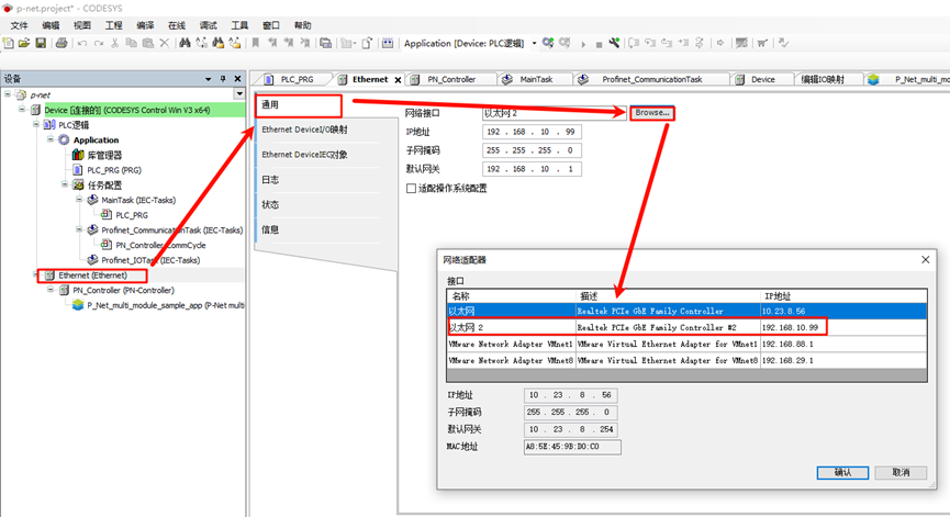
- Ethernet configuration: Double-click Ethernet (Ethernet) on the left navigation panel -> General, and change the network interface to the Ethernet port connected to the development board;
- PN_Controller configuration: Double-click PN_Controller (PN-Controller) on
the left navigation panel -> General, and modify the default slave IP parameters according to the prompts.
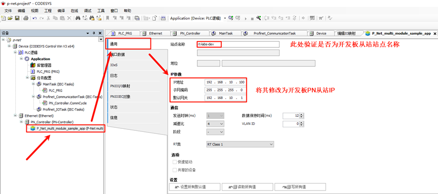
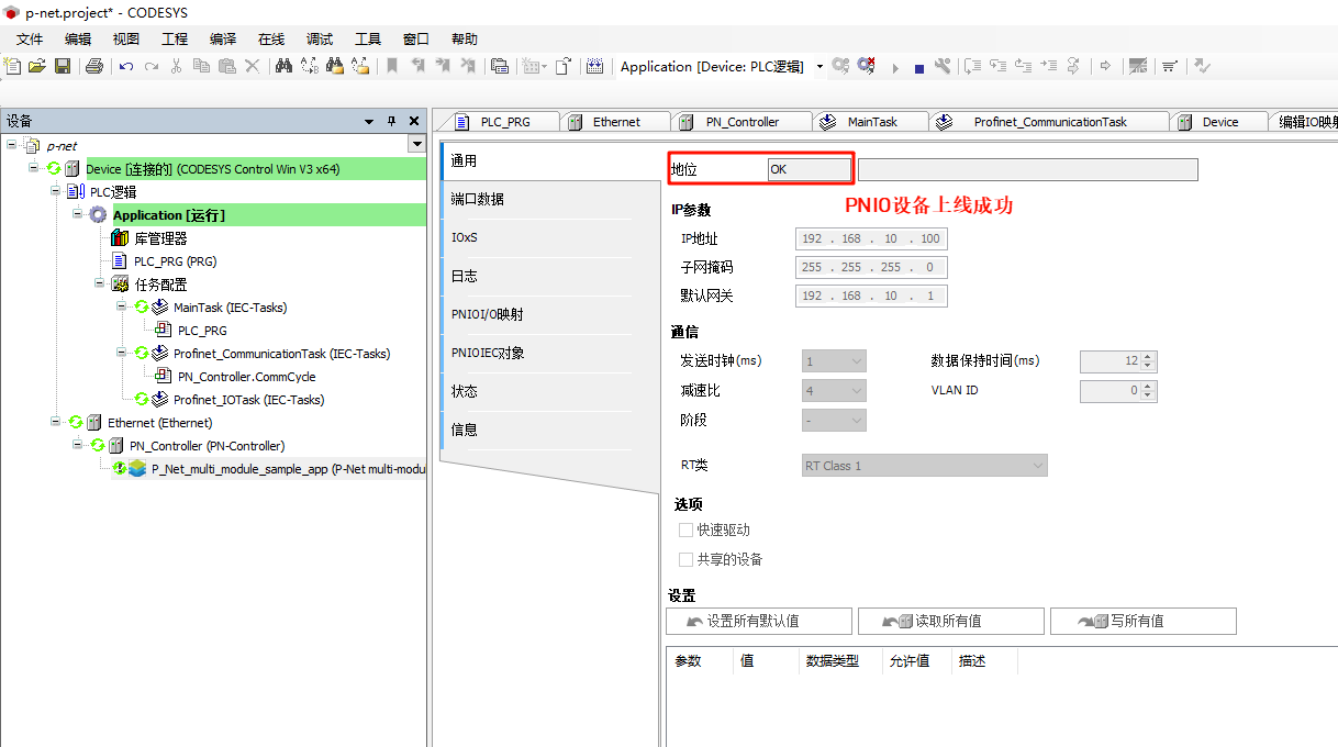
- P-Net Slave network configuration: Double-click P-Net-multiple-module sample app on the left navigation panel -> General, and change the IP parameters to the development board's IP:
4.7 Compile, Debug, and Start the Project
- Step 1: In the project navigation bar, select Build -> Generate Code.
- Step 2: Select Online -> Login.
- Step 3: Click Debug -> Start.
You should now see that the PN master has successfully come online:

5. Profinet Slave Application Startup
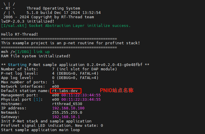
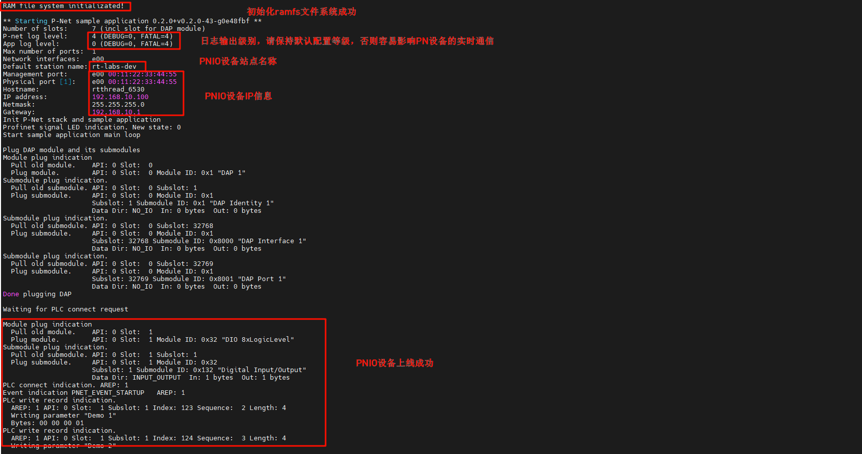
After the development board is powered on, once the NIC link up is detected, the secondary PN station is automatically started:
6. PN Protocol Stack Demo
In this section, we will use CODESYS and PRONETA software to test the interaction between PN master and slave as well as network topology status.
6.1 LED Blinking
Go back to the CODESYS software, select PN_Controller from the left navigation panel, right-click and scan for devices. After clicking on the device name, click Blink LED:

At this point, you will see the log output on the development board (PN slave IO), and the onboard User LED will blink:

6.2 Modify Slave I&M Data
In the device scanning interface, click the I&M button at the bottom left, modify the information, and write the new I&M data:

PNIO will update the slave configuration information:

Click I&M again to see that the I&M modification has been successfully applied!
6.3 PLC Programming and PNIO Control
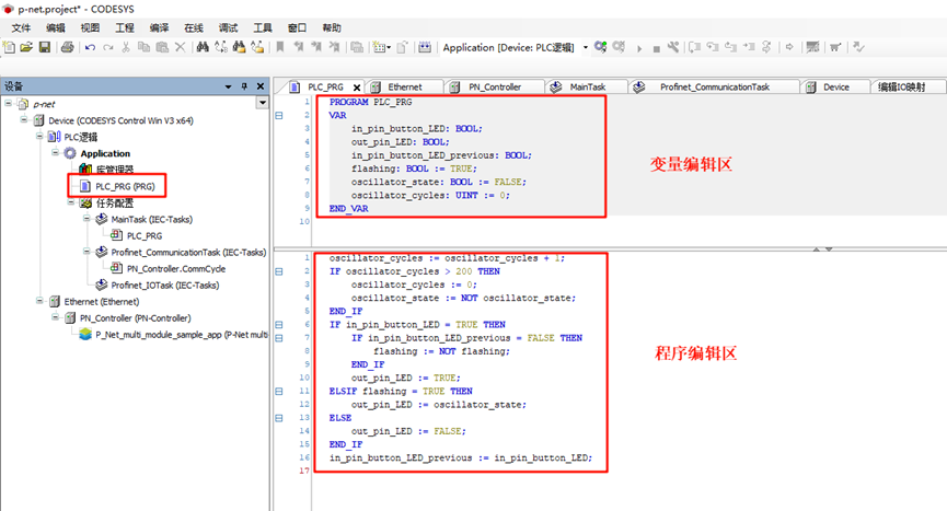
First, click on the left panel to navigate to Device -> PLC Logic -> Application -> PLC_PRG(PRG), and use ST (Structured Text) language to program, defining variables and writing program code:
Variable Definitions: These variables define the input state of the button (
in_pin_button_LED), the output state of the LED (out_pin_LED), and the state variable controlling whether the LED should blink (flashing). The oscillator state (oscillator_state) and oscillator cycle counter (oscillator_cycles) are used to create the blinking effect.PROGRAM PLC_PRG VAR in_pin_button_LED: BOOL; out_pin_LED: BOOL; in_pin_button_LED_previous: BOOL; flashing: BOOL := TRUE; oscillator_state: BOOL := FALSE; oscillator_cycles: UINT := 0; END_VARProgram Definition:
- First, in each cycle, the
oscillator_cyclesis incremented by 1. When the counter exceeds 200, it resets the counter and toggles theoscillator_state(TRUE or FALSE) to create periodic changes. - If the button is pressed (
in_pin_button_LEDis TRUE) and the previous cycle's button state was FALSE, theflashingstate is toggled. This means every time the button is pressed, the LED blinking state will toggle. - If
flashingis TRUE, the LED will blink according to theoscillator_state. Ifflashingis FALSE, the LED will be turned off. At the end of each cycle, the current button state is saved in
in_pin_button_LED_previousto detect the next button press event.oscillator_cycles := oscillator_cycles + 1; IF oscillator_cycles > 200 THEN oscillator_cycles := 0; oscillator_state := NOT oscillator_state; END_IF IF in_pin_button_LED = TRUE THEN IF in_pin_button_LED_previous = FALSE THEN flashing := NOT flashing; END_IF out_pin_LED := TRUE; ELSIF flashing = TRUE THEN out_pin_LED := oscillator_state; ELSE out_pin_LED := FALSE; END_IF in_pin_button_LED_previous := in_pin_button_LED;
- First, in each cycle, the
The configuration in the project is shown in the image below:
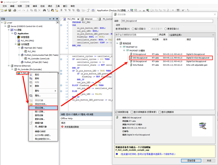
Next, we need to add a built-in I/O module. Right-click on P_Net_multi_module_sample_app and add an I/O module (DIO 8xLogicLevel), as shown in the following image:
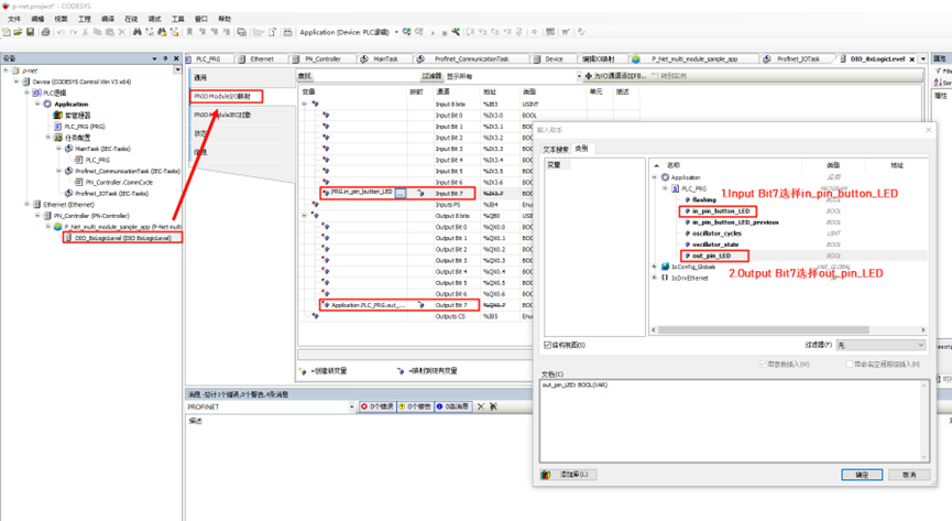
Next, double-click the DIO_8xLogicLevel node, select PNIO Module I/O Mapping, and edit Input Bit 7 and Output Bit 7, binding them to the PLC variables:
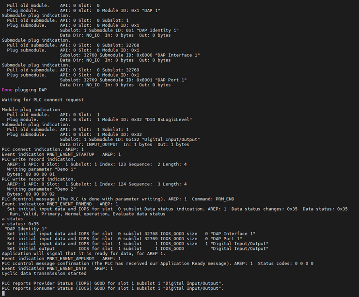
Then, click on the "Compile -> Generate Code" in the top navigation bar, followed by "Online -> Login", and run the program to observe the phenomenon:
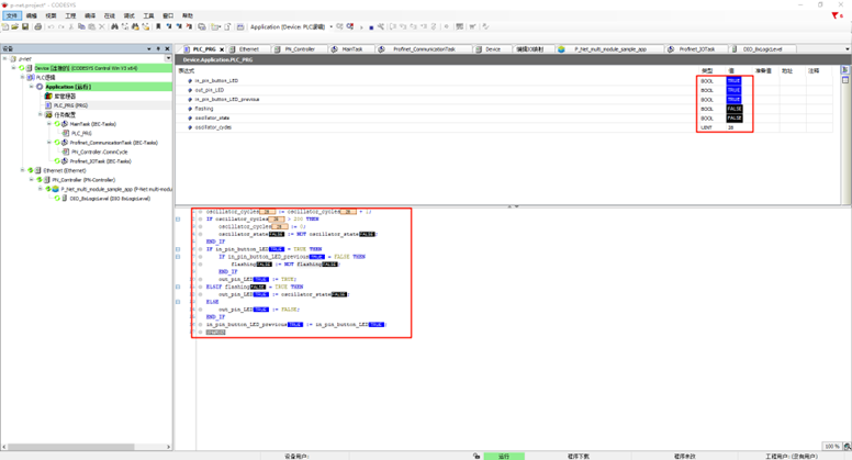
Next, return to CODESYS and double-click on Device -> PLC Logic -> Application -> PLC_PRG(PRG). At this point, you can dynamically observe the program's running status. For example, by holding down the KEY0 button on the EtherKit development board, you can see that the values of in_pin_button_LED and in_pin_button_LED_previous are both FALSE. When you release KEY0, the value of flashing will toggle once.
6.4 PN Network Topology
PRONETA Overview: PRONETA Basic is a simple tool for quickly analyzing and configuring PROFINET networks. It also supports basic testing of ET 200 distributed IO systems and other components.
6.4.1 Install GSDML Files
Open the PRONETA software and add the GSDML file:

After installation is successful, you can see the status information:

6.4.2 Select Network Adapter
Click Settings -> Network Adapter and choose the PN corresponding Ethernet port:

6.4.3 View Online Network Status
Select Network Analysis -> Online from the top left navigation panel, click Refresh, and after a moment, you should see the PN network status. The specific PNIO information can be viewed on the right sidebar. Since we modified the PNIO information in CODESYS, you can also see the updated information here.

Since pnet only supports a single AR by default, we need to disable the gateway device and softPLC device on the CODESYS master:

Then, refresh the device and right-click rt-labs-dev to test the LED and I&M data modification:
